-
Tel : +86-592-6382791
-
Email : sales@pidmaxwell.com
Tel : +86-592-6382791
Email : sales@pidmaxwell.com


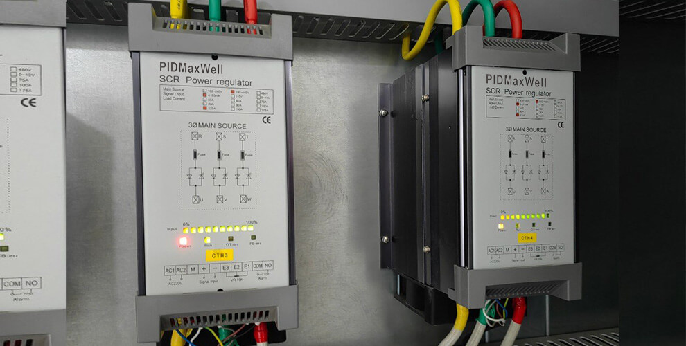
A power regulator (also known as a power controller) is a critical actuating unit in industrial electric heating control systems; its core function is to regulate output power. However, many users overlook a key point: power regulators offer more than one method of power regulation. Different heating loads possess distinct electrical characteristics and process requirements, so the choice of control method cannot be generalized. Common power regulation methods on the market fall into four main categories: phase-angle control (phase-shift control), zero-crossing control (zero-point/cycle control), voltage regulation, and power regulation. Understanding these basic principles helps avoid pitfalls during equipment selection.
Why does the power regulation method affect equipment selection? While the function of a power regulator is to precisely control output power, different loads have vastly different requirements regarding the output method. Standard electric heating elements and resistance wires exhibit relatively stable resistance during operation, making them easier to control; in contrast, loads such as infrared lamps, silicon carbide rods, molybdenum disilicide (MoSi2) rods, and transformers have much more complex electrical characteristics. For instance, silicon carbide rods exhibit a negative resistance region between 700°C and 800°C—where resistance actually decreases as temperature rises—making them highly susceptible to runaway current if the control method is inappropriate. Inductive loads, such as transformers, are extremely sensitive to DC components in the output waveform; excessive DC bias can lead to transformer saturation or even burnout. A mismatch between the regulation method and load characteristics can result in unstable temperature control, abnormal output, excessive harmonic interference, or suboptimal heating performance. The true key to selection lies not in the power rating itself, but in matching the load characteristics with the appropriate power regulation method.
Zero-crossing control (zero-crossing power regulation) triggers the thyristor to switch on or off when the AC voltage is near the zero point, adjusting the output ratio based on complete sine wave cycles. A distinct advantage of this method is that the output waveform remains complete and undistorted, resulting in minimal harmonic pollution to the power grid. Because switching occurs at the voltage zero-crossing point, switching losses and electromagnetic interference are relatively low. It is suitable for standard resistive heating loads, such as electric heating elements, resistance wires, ovens, electric furnaces, and hot-air heating equipment. For applications with high thermal inertia where some fluctuation in power output is acceptable, zero-crossing control is a cost-effective choice. Phase control (or phase-angle control) regulates output by varying the thyristor conduction angle within each half-cycle of the AC waveform. A larger conduction angle results in higher output power, while a smaller angle yields lower power. This method enables continuous, smooth power regulation with high precision; however, it comes at the cost of "chopping" the output waveform, which generates harmonics and causes pollution to the power grid. It is suitable for applications requiring fine-grained power adjustment and continuous regulation, though the electrical environment's tolerance for harmonics must be assessed.
Voltage regulation focuses primarily on altering the magnitude of the output voltage, thereby indirectly influencing heating power. In practice, voltage regulation is often closely linked to phase control technology. Certain specialized loads are sensitive to voltage fluctuations and may require specific voltage regulation methods. For instance, in transformer-coupled heating systems, voltage regulation can minimize inrush current to the load. When selecting voltage regulation, one cannot simply apply the selection criteria used for standard electric heating elements; a careful assessment is required to determine if the load is suitable for continuous voltage regulation.
Power regulation (or power control) emphasizes the proportional adjustment of average power. Rather than continuously altering the shape of individual waveforms, it adjusts the average power delivered to the load by controlling the ratio of "on" time to "off" time over a specific period. Zero-crossing control is a classic implementation of this type of power regulation. Furthermore, power regulation can be categorized into fixed-cycle and variable-cycle modes. Variable-cycle power regulation (also known as cycle-based control) minimizes the control cycle while maintaining zero-crossing triggering; it distributes output waveforms evenly to prevent the grid disturbances associated with concentrated switching. For the vast majority of resistive heating equipment, power regulation is sufficient to meet stable temperature control requirements.
So, how should one choose between these power regulation methods? There is no universal formula for selection; the core principles are to consider the load type and the specific control requirements. For standard electric heating elements and resistance wires, zero-crossing control (a form of power regulation) is generally the preferred choice due to its cost-effectiveness and low interference. In applications requiring more continuous output adjustment, phase control may be considered based on actual operating conditions. When dealing with silicon carbide (SiC) heating elements, it is important to account for their negative resistance characteristics in the 700–800°C range; it is recommended to select a power regulator with a current capacity at least 1.3 times the actual load current. If a transformer is not used, the SiC elements should be connected in series to increase impedance. Loads such as molybdenum disilicide (MoSi2) elements, molybdenum wire, and tungsten exhibit significant resistance changes between cold and hot states, though the relationship between resistance and temperature is linear; a soft-start function (adjustable from 1 to 120 seconds) is recommended to effectively mitigate startup surges. Transformer loads are inductive; particular attention must be paid to controlling the DC component in the output waveform to prevent DC bias saturation. A power regulator featuring soft-start capabilities and zero-crossing triggering is recommended. No single method suits every piece of equipment; the choice depends on the specific application.
Selecting the wrong power regulation method can lead to various adverse consequences: significant temperature fluctuations and instability, where a mismatch between the control method and the load's thermal inertia causes temperature oscillation; slow heating and low efficiency, where the power output mode fails to match load characteristics, preventing the temperature from rising adequately; increased electrical interference, as phase-angle control generates harmonics that may disrupt other precision equipment on the same power grid; and shortened heating element lifespan—for instance, if a SiC element goes out of control in the negative resistance zone, a sudden current spike could instantly destroy it. Equipment damage may also occur, such as overcurrent or overheating in the regulator's internal thyristor modules—potentially leading to immediate burnout—or transformer saturation and failure caused by severe DC bias. Loads requiring continuous voltage regulation may fail to achieve the desired heating effect if an unsuitable control method is used, while even standard resistive loads can generate unnecessary harmonic interference if the control method is poorly chosen.
Beyond the power regulation method, selection requires a comprehensive assessment of factors such as the power supply type, rated current versus load power, control signal type, installation environment, and heat dissipation conditions. Regarding power supply, a distinction must be made between single-phase and three-phase systems; for medium-to-high power applications (exceeding ten-plus kilowatts), a three-phase power regulator is generally recommended to effectively balance the grid load. It is advisable to select a rated current that provides a margin of 1.3 to 1.5 times the actual load current, with even larger margins required for special loads like silicon carbide elements. It is essential to verify that the control signal is compatible with the temperature controller or PLC system. Regarding installation, the power regulator generates heat during prolonged operation; therefore, it must be mounted vertically with sufficient clearance on both sides for heat dissipation. The control cabinet requires ventilation openings for air circulation, and forced-air cooling is recommended when the operating current exceeds 30A. Heat dissipation is critical; inadequate cooling causes the internal temperature to rise continuously, which—even with the correct power regulation method—can trigger overheating alarms or lead to module degradation and failure.
In summary, power regulation methods for power regulators fall into four main categories: zero-crossing control, phase-angle control, voltage regulation, and power regulation. The key to selecting the right unit lies not in the power rating itself, but in matching the regulation method to the load characteristics. Accurately identifying the load type and clarifying control requirements are essential steps to ensure stable operation and a longer service life for the heating equipment.

Address : NO.201 Binhuyili, HaiCang district, XiaMen,FuJian, China 361026
Max liao: +8618150368619(whatsapp)
Email : sales@pidmaxwell.com
Scan via wechat

Scan to Whatsapp