-
Tel : +86-592-6382791
-
Email : sales@pidmaxwell.com
Tel : +86-592-6382791
Email : sales@pidmaxwell.com


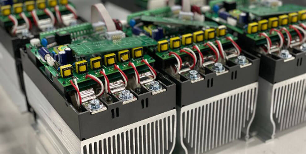
During the operation of industrial electric heating equipment, a confusing scenario often arises: the power controller indicates an output, and a clamp meter detects current—meaning the equipment is not completely cold—yet the heating rate is noticeably slower. A process that once took half an hour to reach the set temperature might now take an hour or longer. In such cases, the power controller is not necessarily the root cause. The power controller is merely one component in the output regulation system; other factors—such as the state of the load, electrical connections, thermal insulation, and production load—also significantly influence heating performance. Equating the mere presence of current with "normal power output" can easily lead troubleshooting efforts in the wrong direction.
I. An output from the power controller does not mean heating power has not decreased.
A current reading from a clamp meter only confirms that current is flowing through the circuit; it does not, by itself, prove that the heating power is normal. Changes in the power controller’s output voltage, the load resistance, or the wiring configuration can all alter the actual power. For instance, if a specific phase previously drew 80A during normal operation, but now draws only 50A—even while the power controller continues to provide an output—the equipment will still heat, but its heating capacity has clearly diminished. Therefore, when observing an output from the power controller, it is best to compare the current and voltage readings against data from a known, properly functioning state. Without a reliable baseline, current values alone have limited diagnostic significance.
II. A partial loss of load downstream of the power controller is a common cause of slow heating.
Large-scale heating equipment typically consists of multiple heating elements, such as heating tubes, coils, or plates. If one or more of these elements fail, the remaining load continues to function, so the equipment does not stop heating entirely. The power controller continues to provide an output, and current remains present, but the total power output has dropped. For example, if a system with a 60kW total rated capacity loses some of its heating elements, leaving only 40kW of active load, the heating rate will naturally slow down. In such instances, you should measure the current and resistance for each individual heating circuit to identify which part of the load has failed, rather than focusing solely on the power controller. III. Evaluate the performance of the power regulator by checking each phase individually in a three-phase system
In a three-phase heating system, measuring only the total current can be misleading, as a drop in load on one phase may be masked by the other phases. It is best to measure the current for each phase separately and observe whether the power regulator’s output is balanced. For instance, if all three phases were previously drawing around 70A, but one phase now shows only 30A, this suggests a potential issue—such as a damaged heating element, a loose connection, faulty contactor contacts, or improper wiring. Comparing individual phases is generally a faster way to identify problems than looking solely at the total current. Note that a balanced output from the power regulator does not necessarily mean that the load on each phase is normal.
IV. Aging heating elements can lead to the power regulator being "falsely blamed"
Over time, heating elements may not only burn out completely but also undergo changes in resistance, oxidation, or localized overheating. When the load resistance changes, the actual current and power output will also shift—even if the voltage remains constant. Consequently, the equipment does not suddenly stop heating; instead, the heating rate gradually slows down over time. This subtle change is easily overlooked and can be mistakenly attributed to a decline in the power regulator's performance. In reality, the power regulator may be functioning perfectly, while the actual issue lies with the load.
V. Poor thermal insulation can cause slow heating, even when the electrical system is functioning correctly
In some cases, the electrical components are in perfect working order, but the problem lies with the equipment itself. Issues such as degraded insulation, damaged door seals, missing pipe insulation, or excessive ventilation can lead to rapid heat loss. Even though the power regulator and heating elements continue to operate at their intended power levels, less heat is retained within the equipment. This manifests as a progressively slower heating rate, difficulty in maintaining a constant temperature, and increased energy consumption. In such scenarios, inspecting the equipment's surface temperature, seal integrity, and insulation is often more productive than repeatedly checking the power regulator.
VI. Changes in production load also affect heating time
Equipment heats up more quickly when empty or lightly loaded; as production volume increases and more material is added, the heating time will naturally extend. This is especially true for metal components, liquids, or other materials with high heat capacity, which require a significant amount of thermal energy to heat up. When comparing heating rates, ensure that the load quantity, initial material temperature, ambient temperature, and process conditions remain consistent. Otherwise, even with an identical power output from the thyristor power controller, the heating performance may differ significantly.
VII. Establish an operational baseline for your power controller; do not rely solely on intuition.
Subjective impressions—such as "it seemed to heat up faster in the past"—can often be inaccurate. Whenever possible, record the time required to heat the system from room temperature to a specific set point (starting from a "cold" state), while also noting the three-phase current, voltage, and ambient temperature. This provides a benchmark for comparison should the equipment's performance change later. Many industrial equipment failures develop gradually; having baseline operational data makes it much easier to identify the root cause when an anomaly occurs.
In short, if a power controller is delivering output but the heating process is sluggish, do not immediately assume the controller itself is at fault. It is worth investigating other factors: is the load intact? Are the three-phase currents balanced? Have the heating elements aged? Has the thermal insulation degraded? Has the production load changed? Determining exactly where the heat is being lost—before deciding on a repair strategy—is far more effective than blindly replacing the power controller.
I. Panel alarms and relay alarms are not the same thing.
Panel alarms are primarily intended for on-site personnel. They indicate that the power controller has detected an anomaly—such as a phase loss, over-temperature condition, over-current, poor heat dissipation, or a synchronization error.
Alarm relays, by contrast, serve as signal interfaces for external systems. They are typically connected to PLCs, indicator lights, buzzers, interlocking circuits, or supervisory control systems. In other words, a panel alarm is a local notification, while a relay alarm is an external output.
While the two may be related, they are not necessarily synchronized at all times. Assuming that "if the panel alarm lights up, the relay must also trigger" can lead to unnecessary complications during troubleshooting.
II. For some power controllers, the alarm relay's behavior is influenced by the unit's operational state.
To prevent "nuisance" external alarms during standby, some power controllers incorporate additional conditions—such as the current operational status, enable signal, main circuit readiness, or the completion of a soft-start sequence—before triggering the alarm relay.
A common real-world example: the control board is powered on, but the main power circuit has not yet been energized. If a power controller fails to detect a complete three-phase power supply, its control panel may indicate a "phase loss." In an industrial setting, however, this might simply mean the unit has not yet been powered on—it does not necessarily signify a malfunction during operation. If the alarm relay triggers immediately, the PLC might misinterpret this as an equipment fault, leading to unnecessary downtime logs or the activation of safety interlocks.
To address this, some equipment is designed as follows: the control panel may display an error while in standby mode, but the alarm relay remains inactive. The relay only triggers if the fault persists once the power controller enters its active operating state.
While this behavior is not necessarily a disadvantage for the end-user, it must be understood in advance, as it directly impacts PLC interlock logic, shutdown strategies, reset procedures, and the determination of responsibility in the event of a fault.
III. Beyond Asking "Is There an Alarm Output?"
From the end-user's perspective, it is essential to clarify the following:
Which alarms appear only on the control panel, and which ones trigger the alarm relay?
Is the alarm relay affected by the unit's operating status, enable signal, or the state of the main power circuit?
Will an error detected during standby mode be signaled to the PLC?
If the same error occurs during operation, is the relay guaranteed to trigger?
Are the alarms "latching" (requiring a manual reset) or "auto-resetting"?
Are there any built-in time delays, signal filtering, or confirmation mechanisms?
Are the relay contacts normally open (NO), normally closed (NC), or changeover (SPDT) types?
What is the contact rating—can it directly drive an external load?
If these details are not documented in the technical specifications, it can easily lead to disputes during commissioning—such as a disagreement over whether an alarm was actually triggered. It is best for the end-user to require the supplier to provide a comprehensive list of alarms, their trigger conditions, terminal definitions, and a logic truth table during the acceptance phase. The clearer the documentation, the lower the risk of unexpected downtime later on.
IV. Always Verify NO, NC, and Common Terminals
Another common issue encountered on-site is a lack of clarity regarding relay contact definitions.
Alarm outputs typically consist of a Common (COM) terminal, a Normally Open (NO) contact, and a Normally Closed (NC) contact. Under normal conditions, the electrical continuity between the Common terminal and the NO/NC contacts is fixed; when an alarm occurs, these states flip. However, because definitions, labeling, and factory settings can vary between different power controllers, one should never rely solely on assumptions or past experience. A more reliable approach is to use a multimeter—under safe conditions—to check the continuity of the terminals. Determine their state during normal operation versus when an alarm is triggered, then compare these findings against the input logic defined in the PLC program.
For instance, if the PLC is wired for a Normally Closed (NC) contact but the program interprets it as Normally Open (NO), the system will behave in an unexpected or "incorrect" manner. The same applies in reverse: the hardware may change state, but the program interprets the signal incorrectly.
V. Synchronized Verification at the PLC End
It is best to investigate alarm issues from both ends simultaneously.
One end is the relay contact on the power regulator; the other is the input point on the PLC. You should verify the following:
Do the relay contacts actually change state?
Does the PLC input indicator light change state?
Do the internal variables within the PLC change state?
Is the program logic configured for a Normally Open (NO) or Normally Closed (NC) contact?
Are the input common terminal, power supply polarity, and the sourcing/sinking (PNP/NPN) configuration consistent?
Are there any loose connections, oxidized terminals, or blown fuses?
If the relay contacts switch correctly but the PLC fails to register the change, the issue likely lies in the external wiring, input power supply, or program logic. If the contacts do not change state at all, investigate the power regulator’s alarm output settings, operating conditions, potential contact damage, or the device's internal logic.
VI. Alarm Relays Are Generally Not Designed for Heavy Loads
Many alarm relays are intended for signal-level output rather than power output. Directly driving high-power devices—such as buzzers, contactors, solenoid valves, or other inductive loads—may work temporarily, but it will likely cause the relay contacts to burn out over time.
A safer practice is to use the power regulator’s alarm relay solely for control signaling, while employing an intermediate relay or the PLC itself to drive the actual load. This protects the contacts, reduces maintenance costs, and facilitates clearer fault isolation; if a failure occurs, only a single relay is affected, rather than an entire control board or production line.
VII. Recommended Sequence for Rapid On-Site Troubleshooting
You may follow this sequence:
Confirm whether the power regulator is currently in standby, enabled, or running mode.
Under safe conditions, trigger a known alarm using an appropriate method.
Observe the display panel and record the specific alarm details. Use a multimeter to test the alarm relay terminals and verify whether the contacts change state.
Observe the PLC input status indicators and the corresponding internal variables.
If the contacts change state but the PLC input does not, check the wiring, power supply, common terminals, and the PLC program.
If the contacts do not change state, investigate the power controller’s alarm output conditions, operational interlocks, parameter settings, and hardware.
Test the reset method to determine whether the alarm clears automatically or requires a manual reset.
Document the results to serve as a reference for future maintenance and system acceptance.
An alarm is more than just a light turning on the front panel. Once a power controller is integrated into an automation system, it directly impacts machine uptime, safety interlocks, product quality, and maintenance efficiency.
To effectively safeguard their operations, users should go beyond simply memorizing wiring shortcuts for a specific product. Instead, they must thoroughly understand the power controller’s alarm indicators, relay activation criteria, contact definitions, PLC input logic, and load-handling capabilities. Request comprehensive documentation during procurement, conduct rigorous testing during acceptance, and maintain detailed records during commissioning. This ensures that if a situation arises—such as an alarm appearing on the panel while the relay fails to act—you can quickly pinpoint whether the issue lies in the design logic, wiring, or software configuration, rather than resorting to blind component replacement, unplanned production downtime, or unproductive disputes.

Address : NO.201 Binhuyili, HaiCang district, XiaMen,FuJian, China 361026
Max liao: +8618150368619(whatsapp)
Email : sales@pidmaxwell.com
Scan via wechat

Scan to Whatsapp